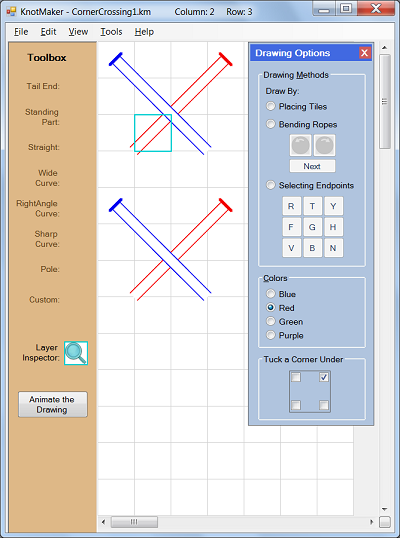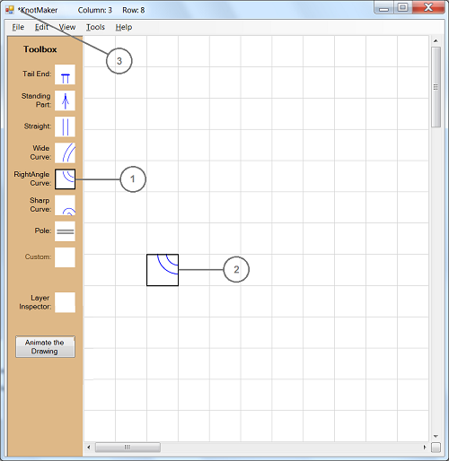
In the above picture:
- Left-click an icon in the Toolbox to highlight it. The picture shows that the "RightAngle Curve" icon is highlighted in the Toolbox, so the RightAngle Curve tile is now the active tile.
- Left-click the canvas to place the active tile into a grid cell. The grid cell becomes highlighted, and its location is displayed in the title bar ("Column: 3 Row: 8").
- The asterisk in front of the word "KnotMaker" in the title bar indicates that the current drawing has been modified but not saved.
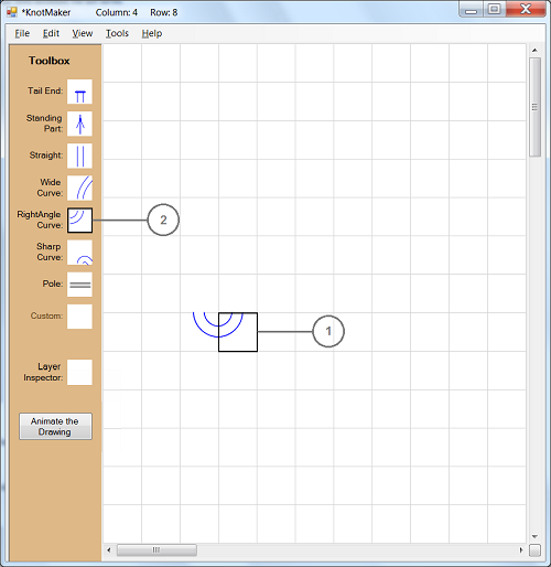
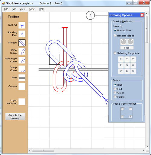
In the above picture:
-
Left-click somewhere else on the canvas to place the active tile into another grid cell.
Right-click a grid cell to rotate the tile clockwise. The picture shows that the highlighted tile in column 4 and row 8 is the same tile as in column 3 and row 8, but the highlighted tile was rotated by right-clicking it.
Shift+right-click a grid cell to rotate the tile counter-clockwise. - You can also rotate a Toolbox icon by right-clicking or shift+right-clicking it before placing the tile onto the canvas.
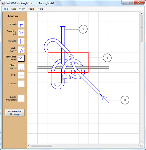
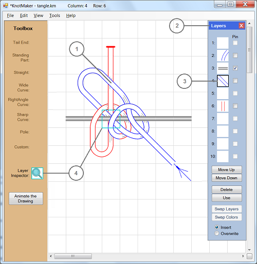
In the above picture:
-
Drag the mouse (using the left mouse button) to draw a red selection border around a group of tiles. You can also use shift+arrows to draw a red selection border around a group of tiles.
To move the selected tiles, drag them to a new location using the left mouse button.
To copy the selected tiles, drag them to a new location using the right mouse button.
While you're dragging the selected tiles, the grid cell that the mouse pointer is in will be displayed in the KnotMaker title bar. - Place a Tail End tile at the tail end (AKA the working end) of every rope. Each rope should have exactly one Tail End tile because some of the KnotMaker functions look for this tile.
- The Standing Part tile shows the direction in which the "standing part" of the rope (i.e. the main part of the rope) is traveling into or out of the knot. All of the KnotMaker functions ignore this tile, so your drawing doesn't need to have any Standing Part tiles. In the screenshots, the standing part is always shown with the arrow entering the knot, but you can show the standing part with the arrow leaving the knot if you prefer.